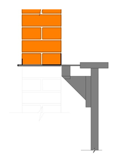
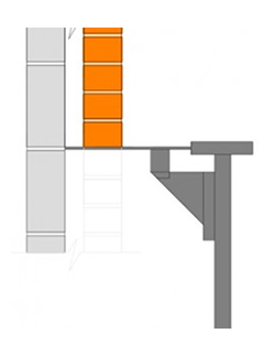
MASONRY WEIGHT AWARENESS CHART INSTRUCTIONS
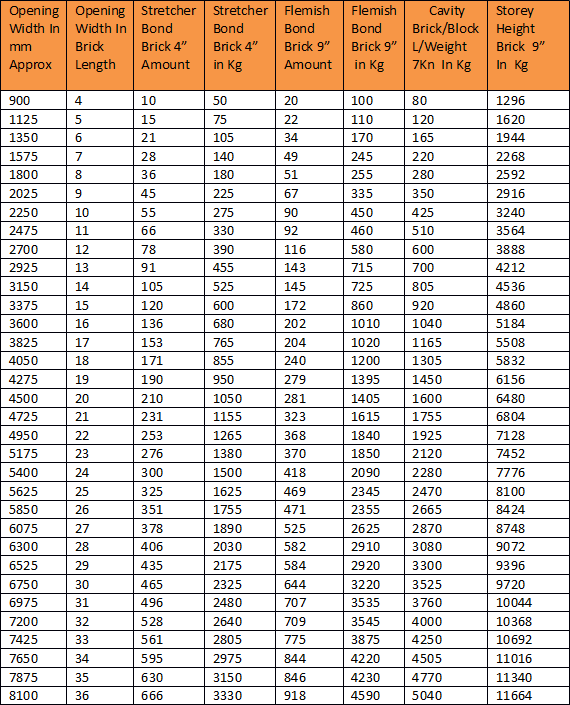
1st Column: Width of opening in mm.
2nd: Width of opening in brick lengths.
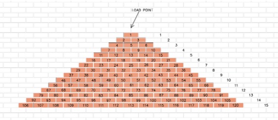
3rd: Number of bricks in a full triangle of masonry above an opening of 102mm brickwork Stretcher bond when a load-point is intact.
4th: Total weight in Kg of brickwork above an opening in a full triangle of masonry within 102mm brickwork Stretcher bond.
5th: Number of bricks in a full triangle of masonry above an opening of 215mm Flemish bond when a load-point is intact.
6th: Total weight of a full triangle of masonry above an opening within 215mm Flemish bond.
7th: Total weight of a full triangle above an opening within a cavity wall, Brickwork and lightweight block work.
8th: Total weight of 215mm brickwork above an opening in a typical 2.4m Storey height in any brickwork bond, half the weight for 102mm brickwork; add 50% for 13” brickwork.
The Brick Brace weight chart is designed for weight awareness to show the difference of the weight of masonry without a load-point and when a load point is intact.
No roof loads are included and a factor of safety of 215mm is included for the different possible positions of a new opening within an existing brickwork bond. 5Kg per brick (F.O.S 1.8) has also been added to allow for the different variety of bricks and the variations of mortar and moisture content.
All lengths over 3,150mm are for propping and bracing. When a load point does not exist every task is different and should be calculated on its own merit. If the size and weight of windows are known the weight of the windows can be added and the volume of brickwork that the windows take up can be removed from the calculation.
Load-Point
A 35 degree angle in a stretcher bond and a 25 degree angle in a Flemish bond from both ends of the opening, carrying up to the central perpendicular joint where both angles meet is the load-point.
All tasks of supporting masonry are different and must be calculated and planned carefully upon their own merit and carried out when using a variety of temporary support equipment most suitable.
–
When an opening is made within an existing wall and a load point is intact the triangle of brickwork above the opening is the only masonry that could collapse and therefore the only masonry that requires temporary support.
–
Upon larger openings where any of the 3 points of the triangle do not remain, this law changes and the weight of the whole storey height sits back over the length of the opening due to the masonry above not having the correct arching effect, this can weigh up to 10 times more than the smaller triangle of masonry.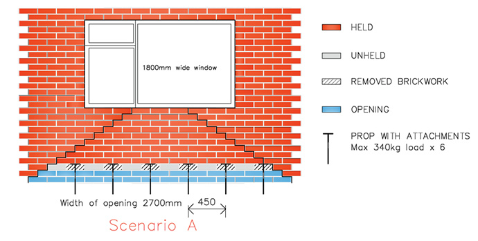
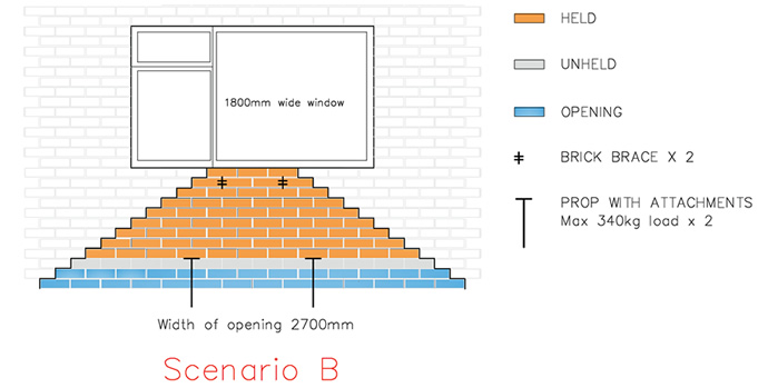
Re-instate A load point
Fit the Brick Brace Safety tool through the broken triangle and it becomes complete, reducing the load to a minimum and safely reducing the number of props required, cost effective without compromising safety.
–
An overloaded prop attachment relies solely on the lateral strength of the masonry of which is always different especially within lime mortars and is why the Brick Brace should be used when possible.
–
The Brick Brace Safety tool increases the variable safe working loads of all the existing propping methods and addresses all the main causes of minor and major collapse during masonry alterations.
–
We are available through e-mail to answer any question regarding temporary masonry support!
–
Propping & needling
Research upon the paper Temporary works toolkit part 10
Carried out by Anthony Lundie
Sent to the author Ray K Filip, The H.S.E’s temporary support team & Veralum
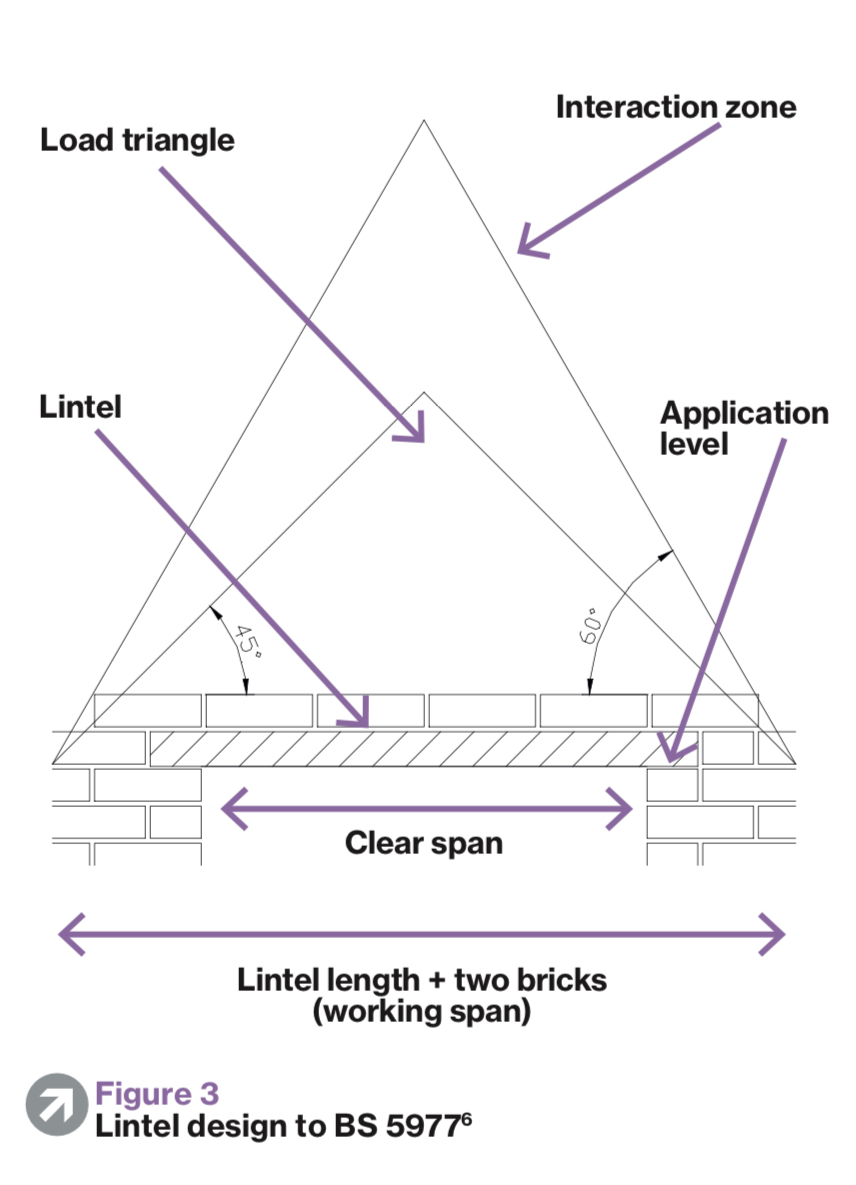
The calculation of temporary support during alterations is only an assumption of a permanent lintel supports calculation, which is incorrect. It doesn’t take into account that every task of masonry alterations is different and that all tasks should be planned carefully upon their own merit. Also the lateral strength of masonry is unpredictable & varies upon every task of which depends upon the length of the new opening required within existing masonry, the mortar mix, the age and quality of the masonry being altered. Within temporary works the masonry has not just been laid and can even be built within a lime mortar mix which has very little (if any) lateral strength upon wider openings.
The 45% angle of the load triangle and the 60% angle of the interactive zone are also different within temporary support works during masonry alterations and vary upon the material used and the bond of the brickwork.
45% Load triangle where a load-point is intact
440mm x 215mm block work is a 45% angle
A 215mm long x 65mm high brick in a Stretcher bond is a 35% angle and 25% angle in an English or Flemish bond.
–
The 60% angle of the interactive zone should not come into play during masonry alterations when all three of the corners of the load triangle are in place as the only masonry that could collapse is this smaller triangle of masonry, therefore this is the only masonry that requires temporary support.
When any of the three corners of the load triangle (25% to 45% depending on the material and bond of the brickwork) are not in place due to no or only one reveal of masonry remaining or a load-point being lost due to impeding windows upon the floor height above, then the calculation would include all of the masonry above the opening, including roof loads & live & static loads where they apply.
–
All existing propping methods rely upon the unpredictable lateral strength of the masonry to work safely which is why a task must be planned carefully upon its own merit and carried out safely by using a variety of temporary masonry support equipment most suitable and not by using the assumed calculation of a permanent lintel BS 5977.
CHECK LIST
- What is the nature of the task, is it remedial works or fitting a permanent support? Is it forming a new opening or increasing the size of an existing opening? Is the opening in a 4″single skin of masonry, two skins or even more? Is the opening in the outer or the inner leaf of a cavity wall or in both?
–
- What is the age and condition of the masonry and what is the masonry material? What design (cavity or solid)? What is the size of the cavity? What thickness is the wall? Which bond is the masonry and which mortar mix, cement or lime?
–
- What are the existing ceiling heights? What are the size and direction of floor/joists, are they load bearing onto the wall or are they non load bearing? Does the existing floor impede the internal fitting access? What is the condition of the internal wall? Is the internal wall plastered or dry-lined or bare masonry as in the case of the majority of total refurbishments? Are there any signs of movement, e.g. cracking?
–
- What height is the opening, ground floor, first floor or higher? Is a permanent support fitted underneath joists? Are the existing joists fitted within the web of the permanent support or is the permanent support fitted at the same height or below non load bearing joists?
–
- What opening size (including bearings) is required? Is a load-point intact? What is the total weight of the load that requires support? Which variety of lintel/s steel/s are specified or most suitable? What are the length, depth, width, thickness and weight of the permanent support/s? Is the permanent support/s deeper than existing floor joist depth?
–
- How will the new permanent support be fed into position and how will any old lintels be removed? Which equipment or variety of temporary support equipment is designed to support the masonry correctly and also provides sufficient fitting work access without dangerously over extending and overloading itself?
–
The more temporary masonry support methods known, the safer and easier the many different specialist tasks of supporting masonry become.
–
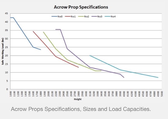
Temporary support equipment options in alphabetical order; Acrow props, Brick Brace, Needles, Prop-Wise and tongued prop attachments.
–
Using the Brick Brace in-conjunction with the traditional propping methods reduces labour & repair time without cutting corners or compromising safety, supports the masonry in between props, stabilises the masonry and also improves the unknown variable safe working load of all the existing propping methods;
Brick Brace with Acrow props, Brick Brace with Needles, Brick Brace with Prop-Wise or Brick Brace with Strongboy’s and depends on the task at hand of which variety is most suitable.
The Brick Brace counter acts all of the hidden problems of only propping masonry.
Forming Openings in Load Bearing Brickwork
Propriety products
No More Props;
Is a steel frame that is cut into 50% of the bed mortar joint above a proposed opening and is suggested in part 10 that it is suitable for creating openings up to 2.5m wide within existing brickwork, when the maximum opening size is only 2.3metres leaving a maximum finished opening for a door/window of only 2 metres when 150mm bearings are required.
Recommendation
This should be rectified with immediate effect.
Strongboy’s
The tool kit part 10 suggests that the maximum opening size for the use of Strongboy’s is around 3 metres and for use in less than heights of 3 metres. The Strongboy instructions have falsely eased a specialist task for 25 years and have suppressed the true level of knowledge that is required to tackle the many different tasks of masonry alterations safely, if they should not be used upon openings over 3 metres, then the Strongboy instructions of use should be changed and include the maximum opening size as does the Brick Brace safety system.
Recommendation
You must inform the H.S.E in writing to ensure the issues are addressed as the H.S.E rely solely on structural engineer organisations due to their own lack of knowledge within this field. I have also attached my professional research of the Strongboy with this research for you to read.
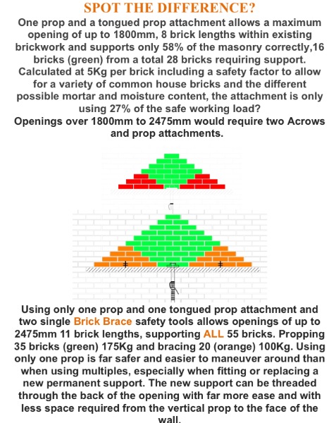
Due to the Strongboy tongue being approximately 155mm wide it doesn’t support all of the masonry safely when fitted at intervals of more than 300mm apart which is why the Brick Brace safety tool/system should also be used when fitted further apart as seen within the illustration below.
Props & Needles
1. It is suggested that needles should not be placed any further than 1 metre apart, is this the author’s personal opinion? As I always assumed that needles were to be placed between 900mm -1200 apart of which depends upon the task, the load and the quality of the masonry? Please clarify.
2. Once again it is suggested that the permanent lintel design to BS 5977 is the calculation used for temporary needles upon large openings. How this is possible when it is only an assumption as the lateral strength of the masonry is unknown and varies upon every task. What is the assumed sum or calculation when either or no reveals does not exist as in the case of many new home extensions due to goal post steel design and what is the correct procedure/sequence when fitting goal posts and box steel designs as this requires further clarification. As a suggestion, the structural engineer that designs boxed steels for the rear of an existing property should provide a correct sequence of works that suit site conditions and should not be left to the unaware contractor as currently done so.
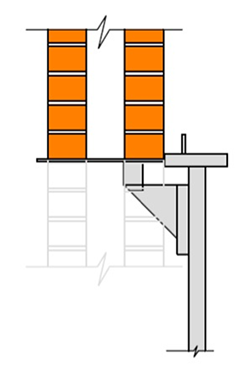
3. Figure 6 (below) is misleading and requires further information as the drawing should have a correct procedure and sequence of works connected to it. Surely the internal end of the lower needle requires packing to floor for support with the lower joists supported down to ground level using the appropriate concentrically loaded equipment. Please clarify, as this error shows how easy masonry support can be misinterpreted due to different parties (author & illustrator) working upon the same subject.

Conclusion
The assumed calculation of a permanent lintel design BS 5977 should not be used by structural engineers for eccentric propping methods with Acrow props during masonry alterations unless the Brick Brace Safety tool/system is also used of which provides further stability to the unpredictable & unknown lateral strength of the masonry.
–
British legislation:
2015 C.D.M, reg19 of which includes all professions within the construction industry, even structural engineer’s, temporary works co-ordinator’s and the H.S.E.
(Temporary Works in Brief)
The builder (contractor) must ensure they have the necessary skills and knowledge and capable of avoiding risks and able to combat risks at source.
Adapt to individual requirements, especially regarding the design of the workplace, the choice of work equipment and the choice of working and production methods with a view in particular to reduce the effect of risk on health and on safety. Adapt to technical progress, replace the dangerous by the non-dangerous or the less dangerous.
Regulation 19
(Stability of structures)
All practicable steps must be taken to prevent danger and ensure that any new or existing structure does not collapse or become unstable due to the carrying out of construction work.
Temporary support must be designed, installed and maintained to withstand foreseeable loads and only used for the purposes for which it was designed for. A structure must not be loaded as to render it unsafe to any person.
Work within health and safety guidelines; respect your legal responsibilities and the welfare of others around you.
The values of The Institution Of Structural Engineers
Professional standards
We endeavour to ensure that our members are highly skilled and work to the highest level by maintaining a commitment to professional standards within structural engineering.
We strive for continued technical excellence; advancing safety and innovation across the built environment.
–
A qualified structural engineer didn’t attend university to design inferior temporary support works so why have IstructE, I.C.E and the H.S.E made it strangely acceptable to prop the rear of a property on a number of over loaded mild steel bendable tongues that sit eccentrically upon a misused Acrow prop and when the obvious accident’s continue to reoccur it’s only the unaware builder that’s at fault and possibly imprisoned where accidents cause injury or fatality?
Where my research & professional opinion is not taken seriously, I believe any future accidents are the fault of Istructe, I.C.E and the H.S.E. due to the inability to adapt to technical progress and using the wrong assumed calculations that do not cover all temporary masonry support tasks due to every task being totally different.
“The world is a dangerous place to live; not because
of the people who are evil, but because of the
people who don’t do anything about it”.
ALBERT EINSTEIN
1879-1955
KEEP IT SAFE, BRICK BRACE.
The Brick Brace is designed as a practicable step to prevent danger, to reduce risk from a task and ensures that any existing structure does not collapse or become unstable due to the carrying out of construction work.
